 Back to GanjaTron's site
Rolleiflex SL35 Light Meter Repair
This web page describes my experience trying to refurbish a light meter on an early SL35 (made in Germany) which uses the original light meter circuit prior to the revision found in later cameras.
Disclaimer
The info on this page is provided with the intent that it may be useful to those experiencing similar problems. No warranty is assumed for personal injury or damage to your camera. If you're not comfortable dismantling precision instruments (yes, cameras fall into that category), have never handled a soldering iron, or lack the proper tools, don't try this. If you're really keen on trying, find a junk camera to practise on first. You have been warned.
There are no explicit disassembly instructions, since I assume those undertaking this repair can figure out how to remove the camera top (at least without destroying it) and dismantle the finder to get at the light meter. If you can't get the top off, you probably shouldn't be messing around inside.
So you can't calibrate your meter?
On a routine inspection of my cameras' light meters, I discovered considerable deviation on the elder of my two SL35's. I removed the camera top and tried recalibrating the meter, but no matter how I set the pots, it was at least 2 stops off in the mid-range. Apparently the CdS photoresistors had deteriorated after 25 years to the point where the circuit was totally out of spec.
Having studied the explosion diagrams and extracts from the SL35 service manual in Prochnow's Rollei Technical Report, I ventured to dissect my SL35. After removing the camera top, dismantling the finder assembly, and desoldering the two photoresistors, I measured their resistances under varying illuminance and noticed differences of over 50%. Closer inspection of the cells revealed that the traces in one of them had begun to dissolve or corrode. Now that was a bad sign!
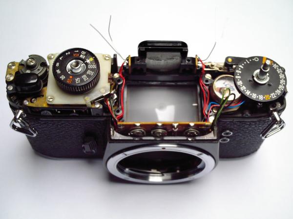
| Fig. 1: The SL35 after removing the top and finder prism. The photoresistors are located in the recesses flanking the finder eyepiece (the protruding leads belong to a pair of replacement cells used for testing), while the meter gauge is located on the right under the counter wheel. The light meter PCB is half visible above the lens mount. Note the recesses in the upper edge of the body for adjusting the potentiometers. |
Light meter circuit
Like most light meters, the SL35's meter circuit is based on the Wheatstone bridge, traditionally used to accurately determine unknown resistances in-circuit by nulling a voltmeter gauge. In a light meter, you actually measure the photoresistor by adjusting another resistance proportional to the exposure (in this case the shutter/film speed dial).
The SL35's meter is rather sophisticated in that it has three adjustable resistances (potentiometers) RI, RII, and RIII (so designated in the original service docs) in each branch of the Wheatstone bridge corresponding to the low, mid, and high ranges, respectively. These are accessible after removing the camera top, located on a small PCB attached to the finder assembly just behind the nameplate. There is also a fixed resistance R0 which presumably also serves to protect against short circuit when the pots are all zeroed. The shutter/film speed dial is coupled to another variable resistor RS and its complement (maximum resistance minus RS) ¬RS. Finally there's the resistance RL of the two photoresistors in parallel, which drops as the illuminance increases. The light meter is activated by the stop down button which is coupled with the lens diaphragm and a switch to close the circuit.
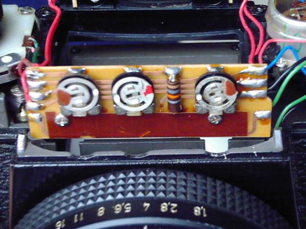
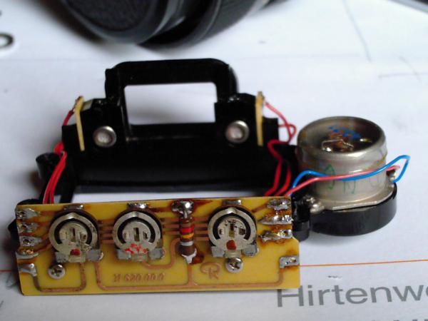
| Fig. 2: Closeup of the light meter PCB with its three potentiometers RI, RII, and RIII (from left to right) for adjusting the low, mid, and high range, respectively, and fixed resistance R0 of 18 kOhms. The finder assembly frame has been detached from the camera body and lifted slightly to fully expose the PCB (mounted to the frame). The PCB is covered with insulation foils at the front and back. |
| Fig. 3: SL35 light meter schematic (made with XCircuit). |
The voltage across the meter in the Wheatstone bridge is characterised by the ratios of the resistances in the branches left and right of the gauge. In the context of the SL35's metering circuit, the following relationship holds when the meter gauge G is nulled:
From this we can see that a decrease in RL (increase in illuminance) requires a decrease in RS (and consequently an increase in ¬RS) by increasing the shutter or film speed in order to maintain equal ratios in both branches and null the meter. Similarly, changing the f-stop on the lens also changes RL and requires adjustment of RS via the shutter/film speed dial.
In my defunct SL35 (serial #4038xxx), RI and RIII = [0..12] kOhms, RII = [0..25] kOhms, R0 = 18 kOhms, with photoresistors in gold casing. There is one other variant on later cameras (notably those made in Singapore) with RII = [0..50] kOhms, R0 = 12 kOhms, and photoresistors in a silver casing, which have a lower resistance curve than the gold ones. The larger resistance range of RII makes it easier to adjust the circuit for replacement photoresistors. According to the Rollei Technical Report, the revised light meter can also accommodate the gold cased ones, and apparently some cameras were delivered with this combination.
Photoresistor replacement
Finding replacement photoresistors turned out to be a formidable task, mainly because the tolerances for the SL35's metering circuit are inherently tight, presumably for the sake of accuracy.
The original CdS photoresistors come in a hermetically sealed, metal-glass TO-46 package which fits neatly into the recesses flanking the finder eyepiece. There is no useful labelling of any kind on the photoresistors, as they were presumably custom made for Rollei. The photoresistor leads are soldered to terminal boards on either side of the finder assembly. Black plastic collars are sandwiched between the recesses and the back face of the finder prism to prevent stray light from entering (which appear to be only marginally effective in practice).
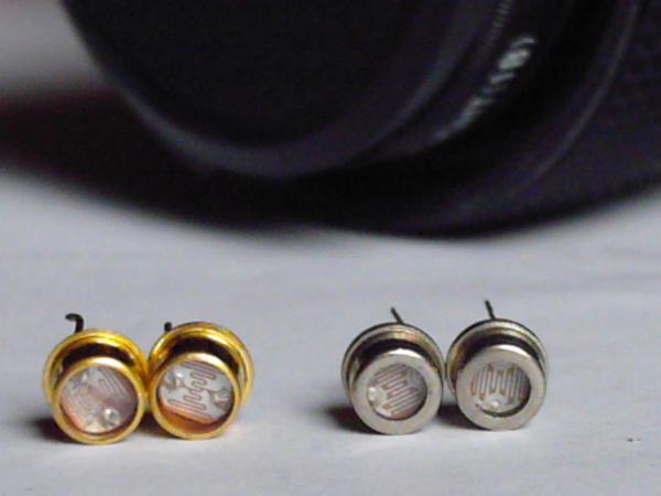
| Fig. 4: The SL35's original photoresistors in the earlier gold-cased and later silver-cased variants. The latter are used in the revised SL35 light meter and have a lower resistance curve. Both cells come in a sealed metal-glass TO-46 package. Apparently that didn't stop the leftmost gold cell from going bad; its traces are visibly corroded. Presumably there were problems early on with these cells, since Rollei must have had some reason to revise the meter and use another photoresistor type. |
I measured the resistance of the (visually) "good" photoresistor using a multimeter, a luxmeter, and a variable halogen light source with diffusor. Obviously this is hugely inaccurate but I hoped it would give me some reference to go by. I then compared this to resistance curves from various replacement candidates (see the plot below). Among the photoresistors I considered were Perkin Elmer's VT200 series (one of very few TO-46 packaged photocells on the market), and their epoxy coated A9060 series.
| Fig. 5: Resistance curves as a function of illuminance for various photoresistors. Plotted are both variants of the original SL35 cells (gold and silver cased), as well as Perkin Elmer's epoxy coated A9060 series. |
To cut a very long story short: after obtaining --with no small degree of difficulty-- and testing over a half dozen photocells in the SL35 along with various replacement values of R0, I had to concede that none of them worked satisfactorily. The circuit simply couldn't be nulled at all, or only in the low range, or otherwise became totally unresponsive to calibration. I simply got nowhere and gave up in frustration. Your mileage may vary...
Light meter replacement
I ended up going the "easy" way -- grabbing a junk SL35 off eBay and replacing the whole light meter. It turned out to be a Singaporean SL35 with the revised PCB and silver photoresistors. Conceivably, one might have been able to find a suitable replacement photoresistor for this circuit due the greater adjustment range of the 50 kOhm potentiometer RII (as opposed to 25 kOhms in the original circuit). However, since it came with a pair of intact cells I simply didn't bother -- I was through experimenting.
Replacing the light meter is not as straightforward as one might imagine, since it requires removing the finder assembly and desoldering the light meter PCB and photocells. Alternatively, one can swap the entire finder (if it's in good condition, which it wasn't in my case), although some soldering is still required. Beware that the wires on the PCB will probably have brittled with age and may snap and need replacement.
Particular attention should be paid to the exposed groundglass under the finder assembly -- avoid dust and scratches at all costs! The finder assembly also mates with three tiny spring loaded adjustment screws for the groundglass alignment. When the finder assembly is lifted off, the springs can fall out along with the entire screen, at which point the fun definitely stops -- watch out!
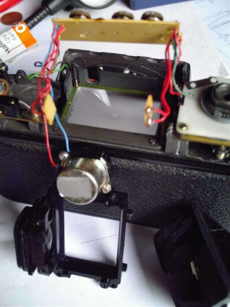 Fig. 6: The removed finder assembly with the attached meter
gauge. The detached light meter PCB is still soldered in. The
groundglass is exposed after removing the finder, with one of the spring
loaded adjustment screws visible in the corner. Note the prism on the
right, which simply drops into the finder assembly's frame and is held
in place by metal brackets. This photo is from the junk (donor) camera.
Fig. 6: The removed finder assembly with the attached meter
gauge. The detached light meter PCB is still soldered in. The
groundglass is exposed after removing the finder, with one of the spring
loaded adjustment screws visible in the corner. Note the prism on the
right, which simply drops into the finder assembly's frame and is held
in place by metal brackets. This photo is from the junk (donor) camera.
|
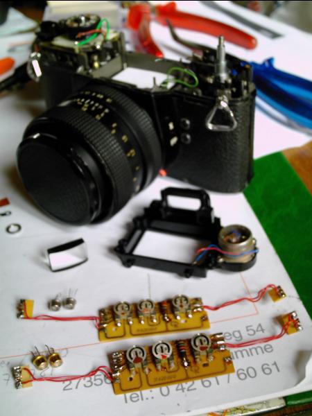 Fig. 7: The original light meter PCB with 25 kOhm potentiometer
RII, 18 kOhm fixed resistor
R0, and gold photocells. Behind
it, the revised light meter PCB with 50 kOhm potentiometer
RII, 12 kOhm fixed resistor
R0, and silver photocells. The
photoresistor terminal boards stick out on the sides. The finder
assembly frame with the meter gauge lies behind the PCBs. Note the piece
of paper covering the exposed groundglass as protection in the camera
body.
Fig. 7: The original light meter PCB with 25 kOhm potentiometer
RII, 18 kOhm fixed resistor
R0, and gold photocells. Behind
it, the revised light meter PCB with 50 kOhm potentiometer
RII, 12 kOhm fixed resistor
R0, and silver photocells. The
photoresistor terminal boards stick out on the sides. The finder
assembly frame with the meter gauge lies behind the PCBs. Note the piece
of paper covering the exposed groundglass as protection in the camera
body.
|
| Fig. 8: The finder assembly frame with the revised light meter PCB. Note that the PCBs are identical in both variants and carry the same part number (31 620 00 0). Only the components differ, with the centre potentiometer RII of 50 kOhms and a fixed resistance R0 of 12 kOhms. The silver cells are already mounted in their recesses flanking the eyepiece. The meter gauge on the right is from the original light meter. |
Light Meter Calibration
The official procedure for SL35 light meter calibration as described in the extracts from the service documentation published in Prochnow's Rollei Technical Report is as follows:
- Set film speed to ASA50 and lens to f/4.
- Mid range setting (EV9): set shutter speed to 1/30th sec, null meter by adjusting RII.
- Low range setting (EV4): set shutter speed to 1 sec, null meter by adjusting RI.
- High range setting (EV14): set shutter speed to 1/1000th sec, null meter by adjusting RIII.
- EV11: set shutter speed to 1/125th sec, check meter and correct if necessary.
Setting the film/shutter speed dial to 1/30th sec and ASA 50 puts it right in the middle of its range (25 kOhms), while setting it at 1 sec and 1/1000 sec covers its minimum and maximum resistance setting. Using a moderate aperture of f/4 rather than wide open also makes sense.
Note that the original values mentioned in the documentation are EV8, EV3, and EV13. This would require setting the aperture to f/2.8, otherwise the light meter is calibrated to underexpose by 1 stop! I have no idea where this discrepancy comes from. Ultimately it doesn't matter, as long as your reference light meter and the SL35 agree. I used a halogen light source with a diffusor hooked up to a variable power supply and my trusty Lunasix as reference meter for adjusting the source to the desired EV. Not terribly accurate, but close enuff.
Precautions
- Avoid touching the groundglass or letting parts drop onto it. The smallest scratch will be magnified and clearly visible in the finder! To be safe, drop in a piece of paper cut down to size to protect the groundglass while working on the meter.
- Avoid touching the exposed glass surfaces of the prism.
- Beware of the tiny springs around the three adjustment screws for groundglass alignment underneath the finder / light meter assembly! The screws mate with the assembly frame and have to be cleared before the assembly is free. Don't mess with these screws otherwise you'll have to realign the screen. Don't turn the camera over, or these springs, the tiny washers on which they rest, and the entire screen with its frame will spill out! You'll have a jolly good time putting all this back in place...
- Remove the battery before soldering and keep soldering time to a minimum to prevent damage to the photoresistors.
- Beware of stray light during light meter calibration, since it has to be done without the camera top. Shield the prism with your hand. Don't forget to fit the plastic collars between the photocell recesses and the prism.
Back to SL-35
Back to GanjaTron's site(c) Copied Right 2006 by GanjaTron